Detailed Instructions
Software version 2.2 provides the facility to have sources N.MUSIC and N.RADIO using the BeoLink PC 2 or Beoport and was developed for BeoSound 9000 Type 252x (from April 1996) and Type 256x (from September 1998). BeoSound 9000 Type 257x (from June 2001) already has the necessary software to support N.MUSIC and N.RADIO commands. The software 2.2 for both BeoSound 9000 Type 252x and 256x has the same part number of 8344087
These instructions are assuming you have:-
- An understanding of the anti-static requirements needed for the safe installation of the software update
- A size T8 splined screwdriver set
- The software update kit
- The Beosound 9000 is in front of you with the glass door nearest you and the control panel at the top right away from you. All subsequent instructions are assuming this positions.
With the power on the unit in the horizontal position (not vertical) and before anything has been unscrewed trigger the playing of one of the centre two CD's and press the button to open the glass door, then turn the power off. The power cord should now be disconnected and the sledge should now be in the middle on the unit with the door open.
STEP 2
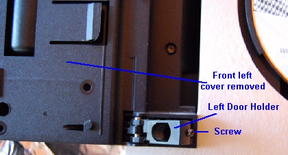
Using your size T8 splined screwdriver unscrew the hinge screws on either side of the glass door. The picture below shows the left hand hinge. You will need to turn the screw about three (3) turns anti-clockwise, holding the door. It should be noted that the right hinge does not move as it is connected to the door drive, but the left hand hinge will move.
STEP 3
Remove the control panel completely by pressing the plastic button on the centre right and lifting it out of the socket. To the left of the control panel is a blanking panel which must also be removed by sliding it left about 1" (2.5 cm) and then away.
STEP 4
With the T8 splined screwdriver remove all the screws which are behind the control panel and blanking panel plus two screws (left and right above disk position 1 & 6) behind the top half of where the glass door was before it was removed.
STEP 5
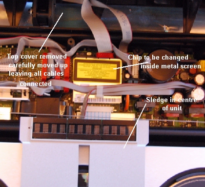
The top plastic cover can now be carefully removed which will then expose the main printed circuit boards as below.
STEP 6
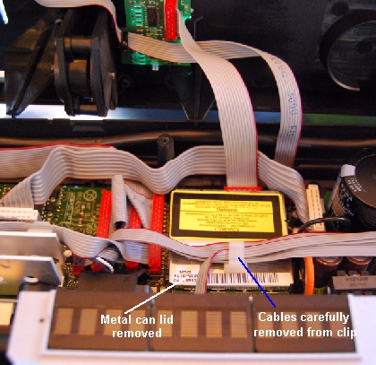
Carefully slip the ribbon cables from the clip on the top of the screen can and remove the screen container lid which is just a push fit.
STEP 7
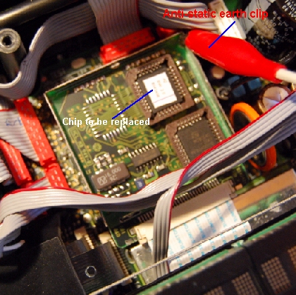
With the screen lid removed the chip to be changed is exposed as below. Notice the anti-static earth clip which has been connected to the metal box and you should be wearing you anti-static wrist strap as well.
STEP 8
Remove the plugin chip with a plastic chip remover and plug the new chip in is place. Note that the top left hand corner of the chip has a very small 45 degree cutoff to ensure it goes in the correct way. With the chip the correct way around firmly push the chip into the socket. The picture below shows the position of the 45 degree cutoff on the chip
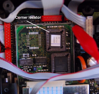
With the chip installed and the screen lid replaced put the unit back together using the instructions above in reverse.
When you come to putting the Glass door back on, screw the right hand hinge first while holding the door, then the left one. Now its just a matter of testing that everything is working correctly.
